Unpacking my own misconceptions about circuits
When I volunteered to teach an electronics class this year, I knew I’d be faced with re-learning some concepts I had never correctly learned. Although I have a degree in Computer Engineering, if I’m completely honest, I struggled in my own electronics classes. I muddled through with decent grades. But I knew then, and I know now, that I never conceptualized what electricity is and what the measurements mean. I survived by memorizing formulas as best as I could.
This year, I’ve had to re-learn concepts such as voltage, resistance, and current, so I can figure out how to teach them to students -and give them a chance at grasping the ideas better than I did.
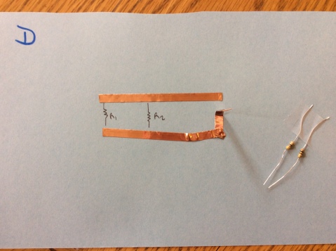
To learn about series resistance, I gave groups of kids cardstock paper, copper tape, a coin cell battery, a handheld multimeter, and two “mystery resistors” – a 1 kOhm and a 220 Ohm. Their task was to measure voltage and resistance at several points in the circuit, and figure out a math formula that would describe how the voltage and resistance related. The circuit looked like this (the coin cell battery goes under the tape in the corner).
Here’s where I put my disclaimer. I had totally forgotten the formulas for voltage and resistance in a series circuit or parallel circuit. I knew they worked differently from each other but wasn’t sure what I was going to find when I tried this experiment. I purposefully did not look up the formulas before I tried the labs for myself. I wanted to see if the math was intuitive and if kids would be able to figure out the formulas.
I ended up discovering things about circuits and how electricity works that I never, ever understood when someone gave me formulas. I really wanted the kids to see it. It made me really excited to finally have the light bulb come on.
Here’s what their data looked like (it was really similar to what I got when I tried the experiment).
Students at first noted “when the resistance goes down, the voltage goes down.” I encouraged them to delve deeper. This is what they said:
“There are about 400 ohms for each volt.”
“I get the same thing when I divide the voltages as I do when I divide the resistances.”
“When I divide the voltage by the resistance, I get 0.0025 for both.”
“The voltages add up to the voltage of the battery.”
The 3 volts were split between the two resistors by the same ratio as the resistances. Since the resistors had almost a 5:1 ratio between them, the voltage drop across them was also split 5:1 and the total added up to 3 volts.
I gave the kids a follow-up challenge. Go dig through my box of resistors and pick out two different resistors to put in your circuit such that the voltage across one is twice as much as the voltage across the other. Groups that thought the 400 ohms per volt ratio was important had a tougher time with this task. The ones that saw the ratio between the voltages and resistances had an easier time. It also forced them to consider unfamiliar units such as kOhms on the labels.
Most groups were successful with this task, and I had them report what resistances they used:
1 kOhm and 470 Ohms
220 Ohms and 100 Ohms
4.7 Ohms and 10 Ohms
100 kOhms and 220 kOhms
For each group, the voltage drop was about 2V across one resistor and 1V across the other, for a total of 3V – the voltage of the battery.
I decided to go on to parallel circuits. I remembered, vaguely, that the voltage drop was the same across resistors in parallel, but that this drained the battery faster. I couldn’t remember the formula for the effective resistance across the parallel resistors. I got out my batteries and box of resistors, and built a few circuits for myself to see if I could see the relationship, and once I did, I got really excited. Here’s what I found. See if you can identify it.
The resistance drops when you put both the resistors in parallel. I noticed in the first circuit, the resistance dropped by 1/4 of the 100-ohm resistor. And that 100/(330 + 100) was about one-fourth. In the second circuit, the resistance dropped by about a third of the 100-ohm resistor. 100/(100+220) is about one-third. Same pattern with the third circuit.
I had a memory of a problem I used to give kids when I taught math. There’s a fish tank. Hose 1 can drain the fish tank in 6 minutes. Hose 2 can drain the fish tank in 12 minutes. How fast will the tank drain if the two hoses work together? I remembered the answer was counterintuitive – your first hunch is to average the times, but then when you think about it, that answer is nonsense. It would take less than 6 minutes for the tank to drain if the 6-minute hose had some help. But it wouldn’t be 3 minutes, because the 12-minute hose wouldn’t quite cut the time in half.
If I thought of the problem the same as my resistor problem, I would think the answer is 4 minutes. The hose with less resistance takes 6 minutes. If I consider the ratio 6 / (6+12), I get about 1/3, so I should cut the 6 minute time by a third and make it 4 minutes. What if I solved this the way I solved the fish tank problem back then?
Holy crap. I went through high school physics and years of college electronics classes without ever appreciating what this math meant. We know a circuit is a flow of electrons, because the math behind circuits works exactly in the same way as the math behind the flow of water. This was an epiphany for me and a turning point in my relationship with electricity. Resistance is, in a way, a measure of the amount of time it would take that element to drain a battery – in the same way you can measure the resistance of a hose by the amount of time it would take to drain a water tank.
I made a resistance lab for the students, and I wanted them to see if they could identify that same relationship. In this one, I gave each group a card with a parallel circuit drawn on it, and two mystery resistors.
Their task was to identify the resistors, then attach them to the circuit as shown and measure the effective resistance and voltage across both. Each group got a different set of mystery resistors. All groups edited the same Google Doc so they could all see each other’s answers. I did not have a group D2 or E2. I was so pleased with how professional and serious they were while editing the Google Doc together (we worked on collaboration ethics beforehand). Here are their results. The rainbowy text at the top was added by a creative student.
Before they summarized their final sentences, I gave them the fish tank problem. I will keep working with them on that conceptual understanding of electricity as a flow, because I know it took me several hours of exploring before I had my lightbulb moment. They’re coming along though. I can tell by reading their responses that they did some good thinking.
I did, eventually, look up the formula for effective resistance in a parallel circuit.
It’s the same math as the fish tank problem. Electricity is a flow. How did I not get this before?
I’m going to assert right here that when you teach students to memorize formulas instead of understand broad concepts, it’s worse than sloppy teaching. It actually does damage to students and harms their problem-solving ability. I never want to do this again.
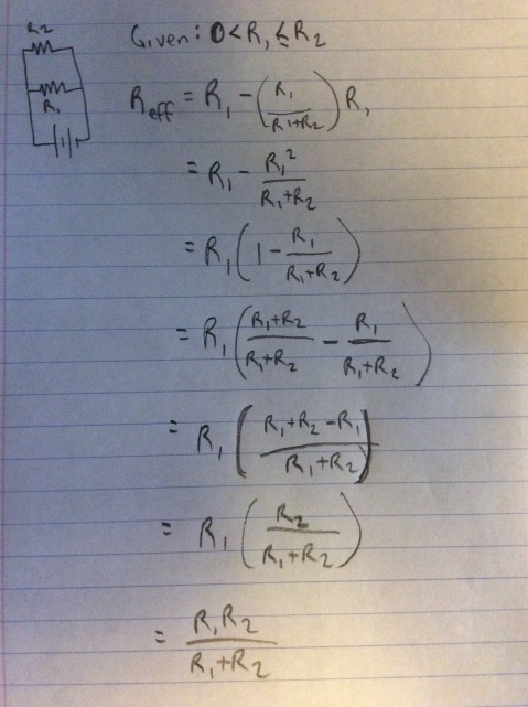
I did some work to prove to myself that this math was the same as my original intuition: that you could also find the effective resistance by using the formula: R1 – (R1 / (R1 + R2))*R1 where R1 is the smaller resistance.
For fun, here’s that work.


Recent Comments